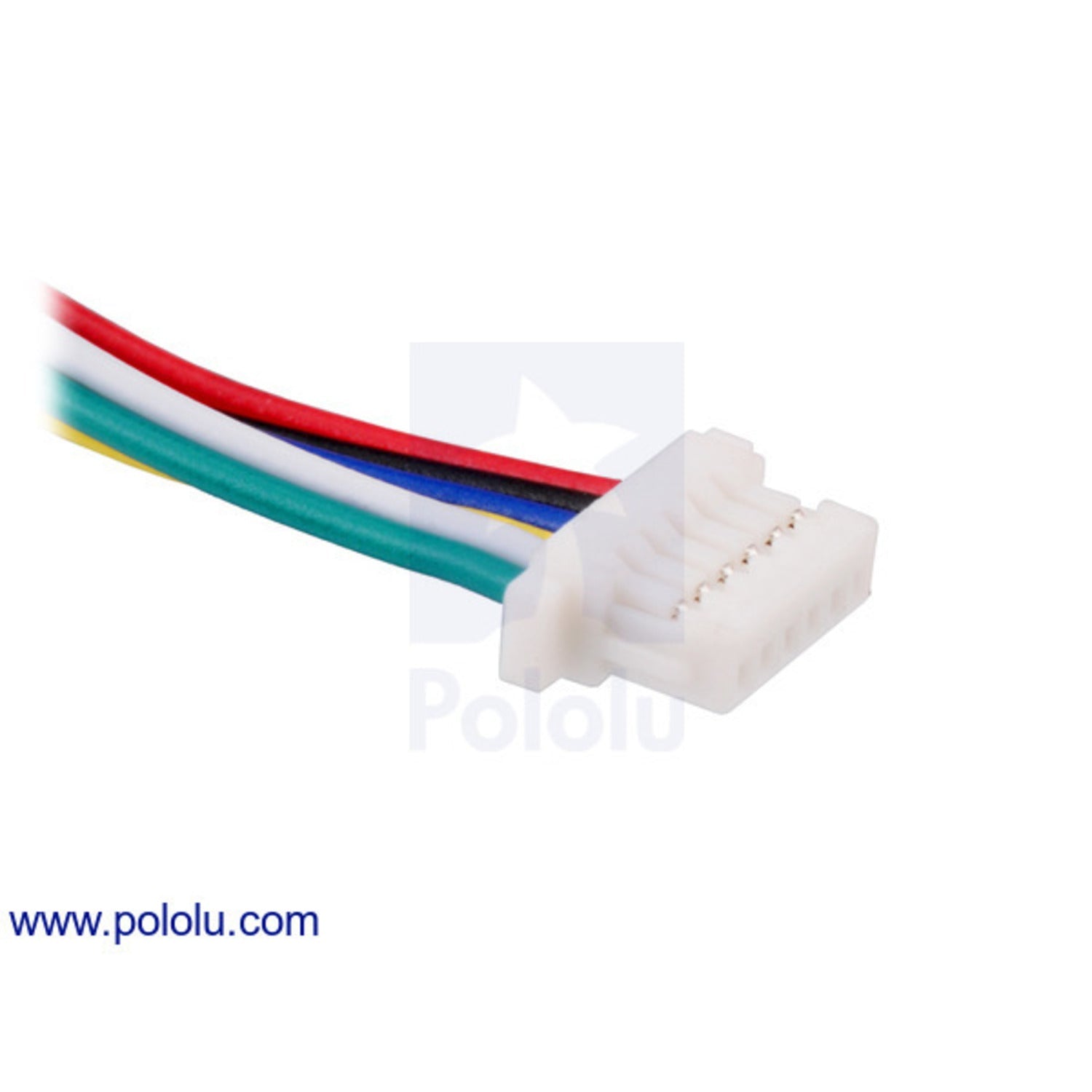
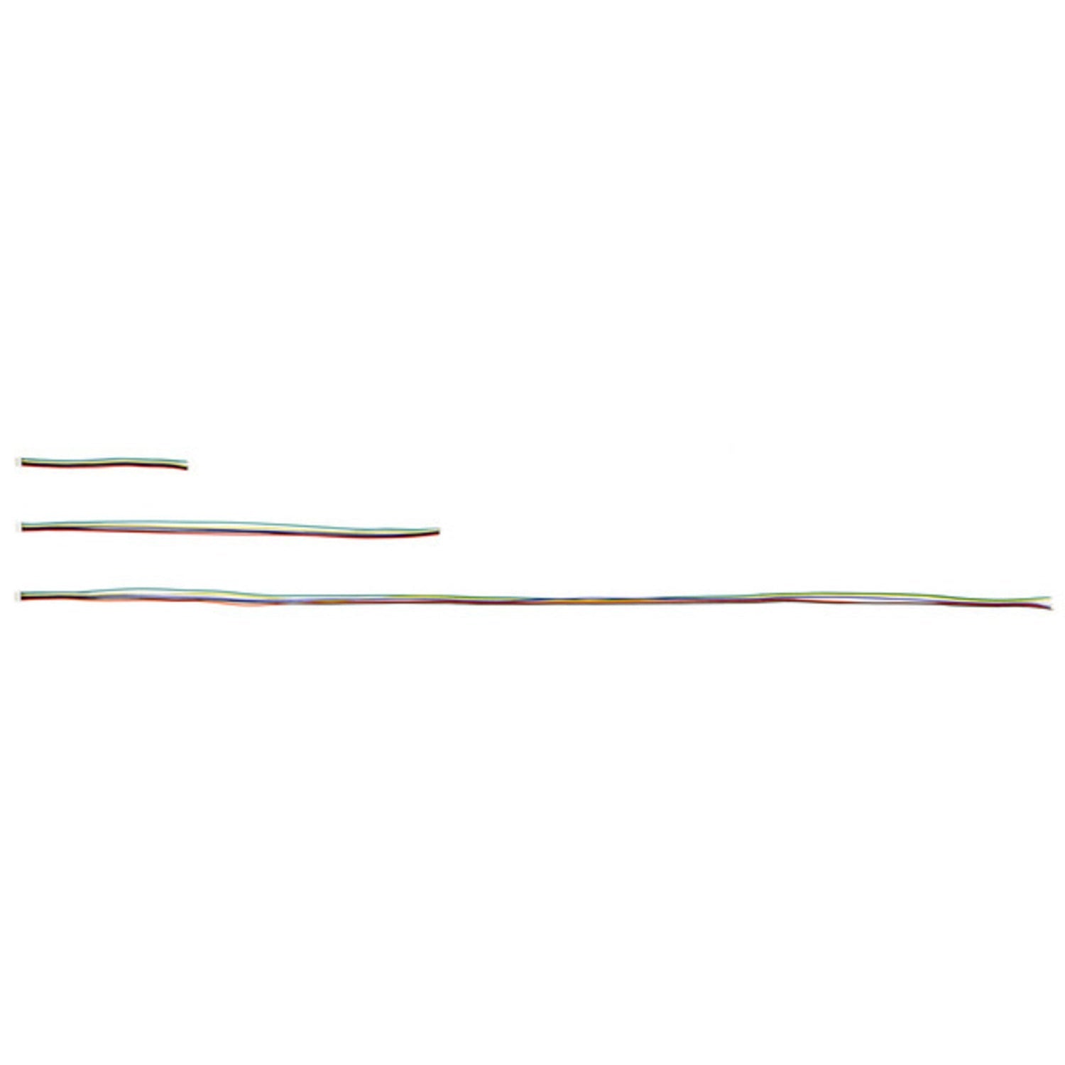
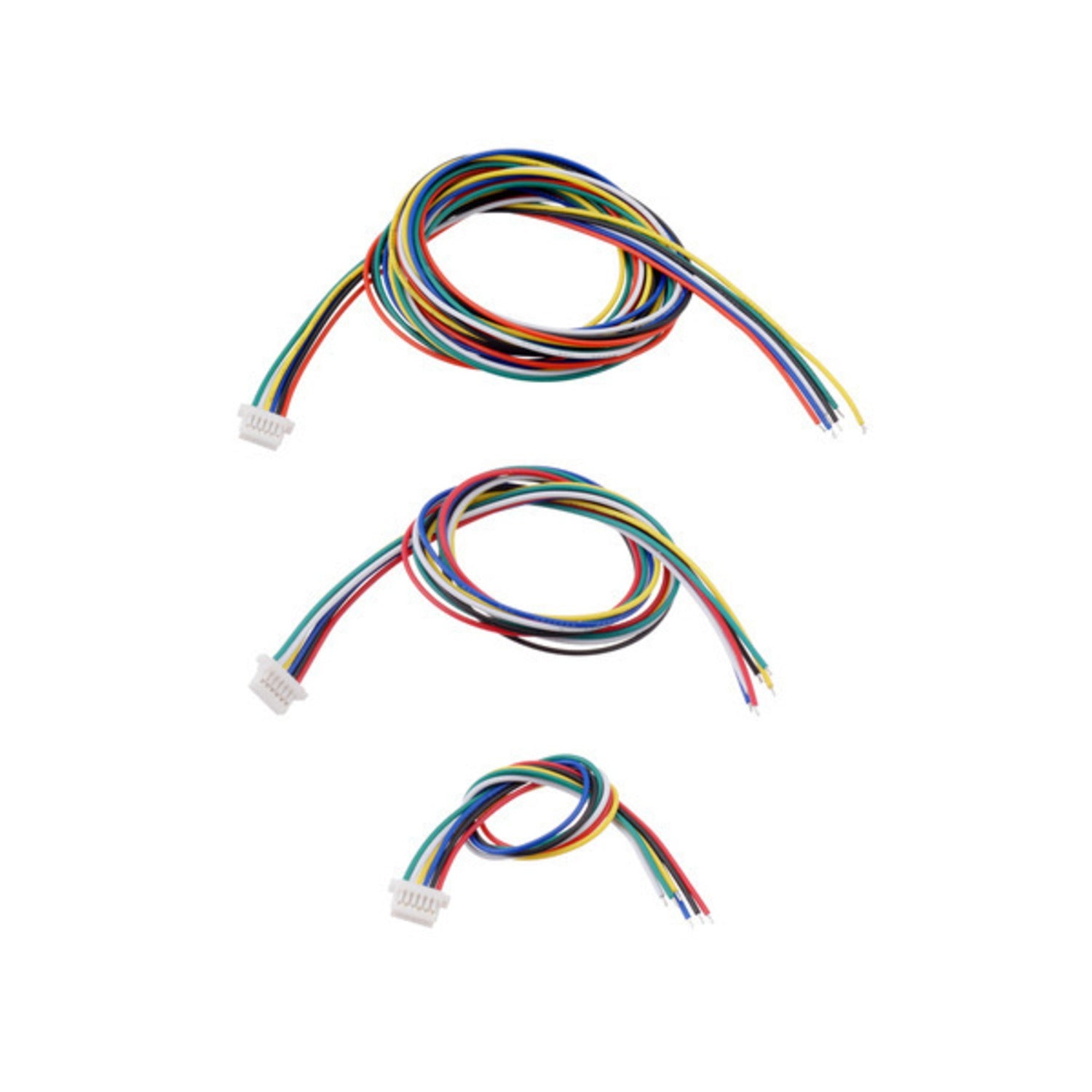
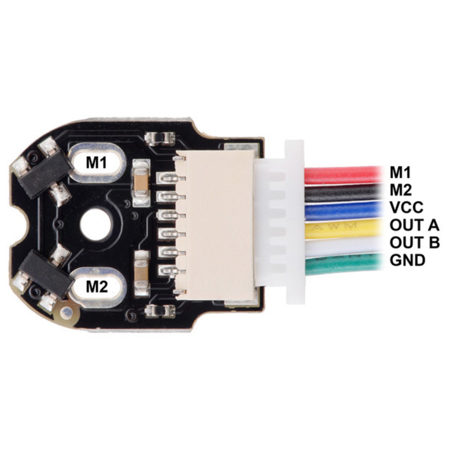
This 30cm cable is a perfect match for our Micro Metal Gearmotor Encoders, whether they have a top - entry or side - entry connector. It's made up of six 28 AWG color - coded wires. One end features a female JST SH - type connector, while the other end is unterminated. You can easily cut it to fit your specific needs. With our male or female crimp pins and crimp connector housings, you can create a connector for the unterminated end that works well with standard solderless breadboards, perfboards, 0.1″ male headers, and 0.1″ female headers. When used with our encoders, here's the wire color scheme: Red is for motor power and connects to one motor terminal, Black is also for motor power but connects to the other terminal, Blue is for encoder Vcc, Yellow is for encoder A output, Green is for encoder GND. We offer this cable in three lengths: 12 cm (4.5″), 30 cm (12″), and 75 cm (30″). Check the encoder product pages for more encoder usage info.


Using this cable is easy. First, identify which type of Micro Metal Gearmotor Encoder you have (top - entry or side - entry). Connect the female JST SH - type connector end to the encoder. The other unterminated end can be cut to the length you need for your project. Then, use our provided crimp pins and connector housings to make a connector that fits your breadboard or headers. When connecting to the encoder, follow the color - coding we've provided. Red and black wires go to the motor terminals, blue for powering the encoder, yellow and white for encoder outputs, and green for grounding. Remember to handle the wires gently to avoid damage. Keep the cable away from sharp objects and extreme temperatures. If you notice any fraying or damage, replace the cable promptly. This will ensure the cable works well for a long time and your encoder functions properly.