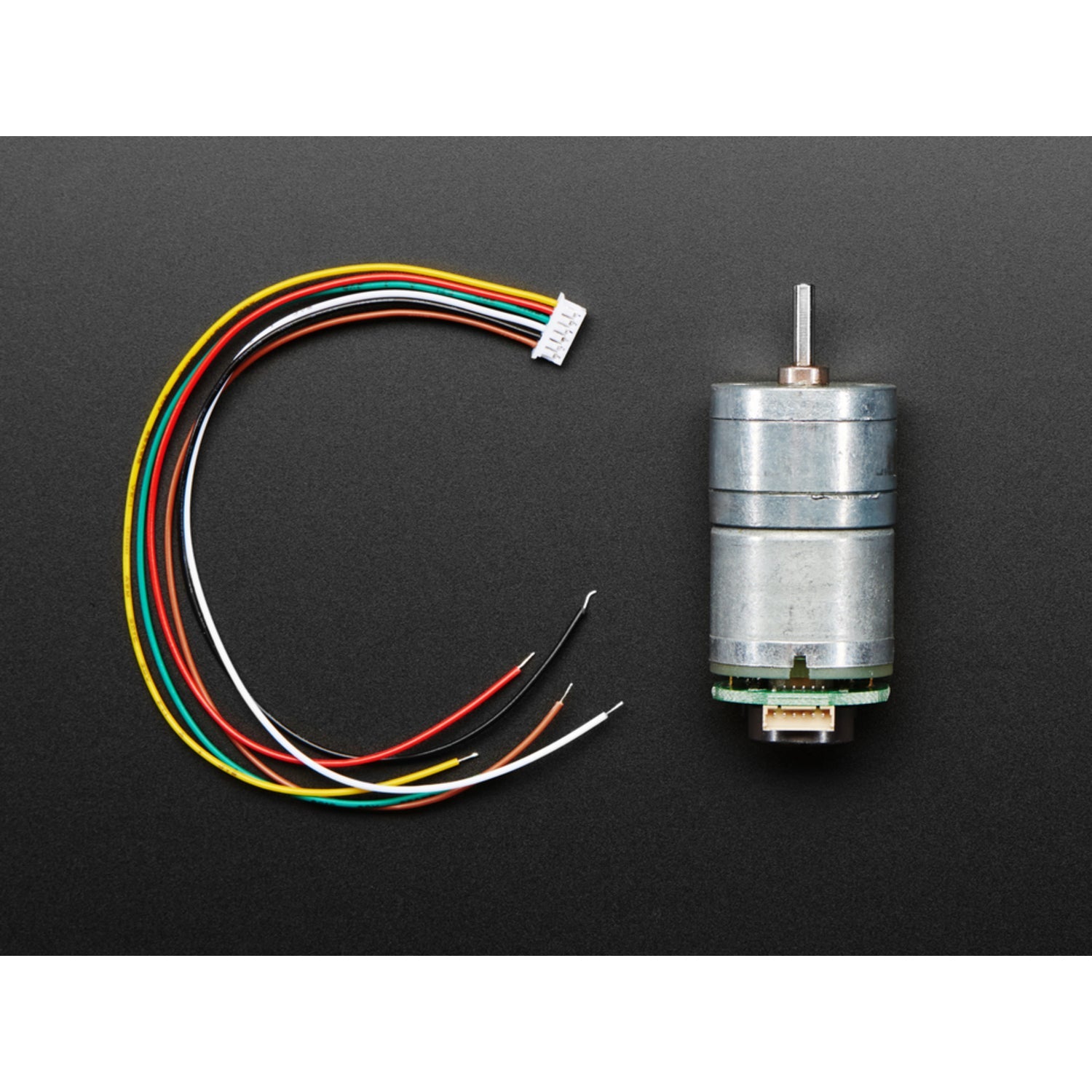
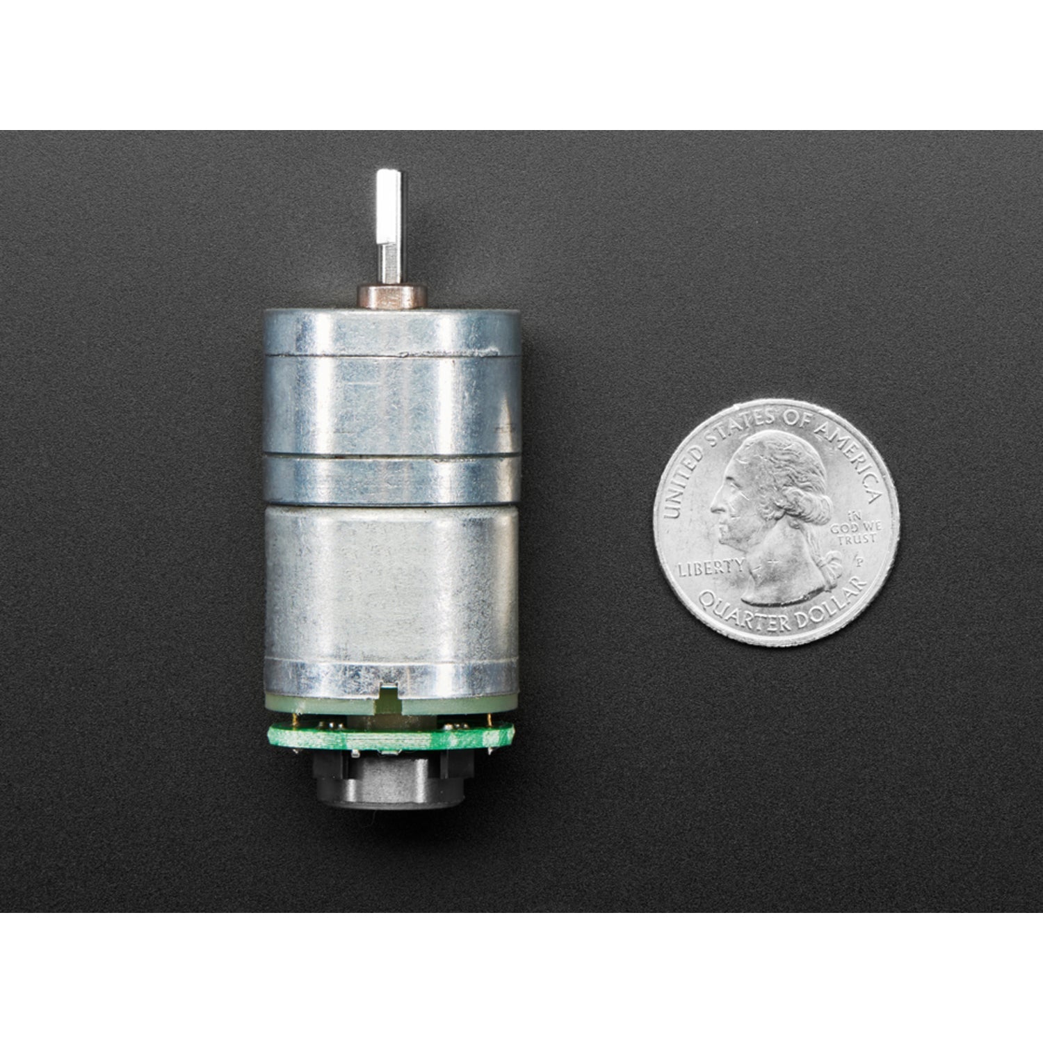
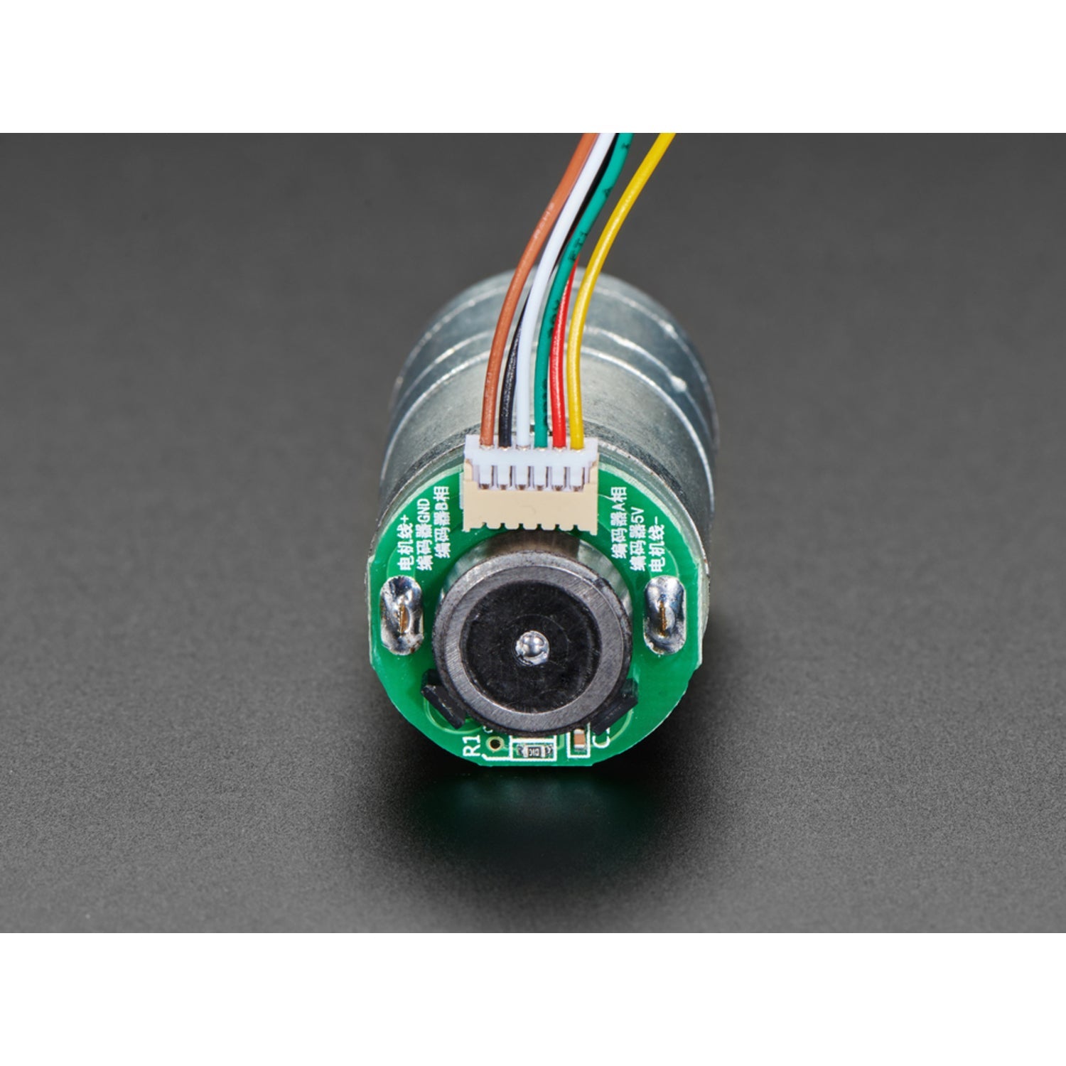
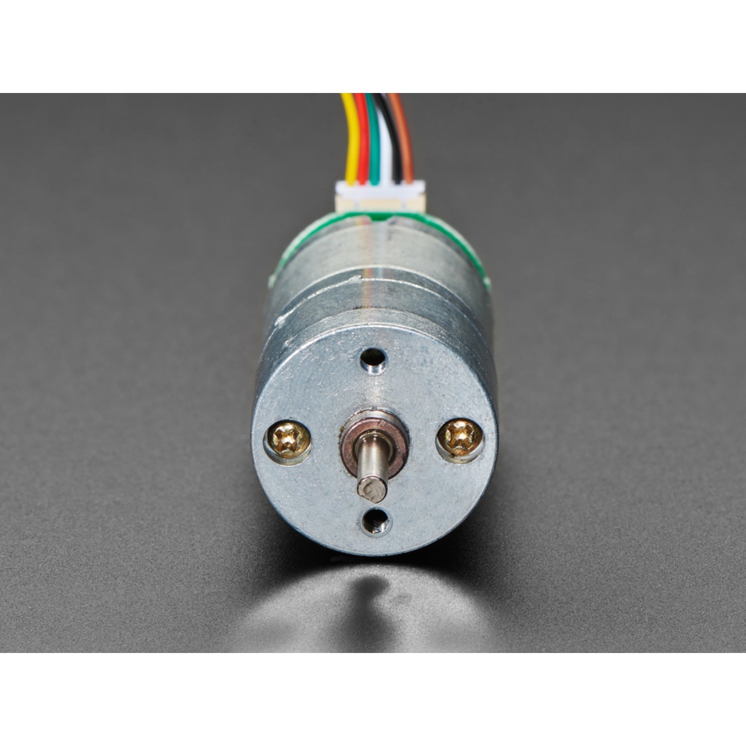
In a robotics project, getting a motor to spin is just the start. You'll soon find that motors can vary in speed, even those with the same part number. Voltage, environment, and manufacturing differences all play a role. So, the next step is to measure the motor's speed. Adding an encoder wheel and an optical or magnetic counter is a great way to start. As the motor rotates, the encoder wheel spins, and the counter detects each spoke, allowing your microcontroller to count and figure out the speed. For even better results, add a second counter to determine both speed and direction. Wiring can be a hassle, but this motor simplifies things. It comes with a magnetic wheel and two hall effect sensors pre - attached. It's not only easy to use but also a powerful motor. Supply 7V DC to the brown and yellow wires, which connect to your motor driver. You can use an H - bridge to adjust speed and direction with PWM. Connect the black wire to your microcontroller's ground pin and the red wire to 3 - 5VDC. Then read the hall effect outputs on the white and green wires. We have an Arduino example sketch that can be adapted to other languages. Just interrupt on one of the encoder pins, count the time since the last interrupt, and multiply by 12 counts per revolution and the 1:20 gear ratio.


Using this motor is simple. First, connect the brown and yellow wires to your motor driver and supply 7V DC. You can use an H - bridge to adjust the speed and change the direction. Remember to connect the black wire to the ground pin of your microcontroller and the red wire to 3 - 5VDC. To measure the speed and direction, read the outputs on the white and green wires. We've got an Arduino example sketch that you can modify for other languages. As for maintenance, keep the motor clean and avoid exposing it to extreme temperatures. If you notice any strange noises or performance issues, check the wiring first. And that's all you need to know to get the most out of this great motor.