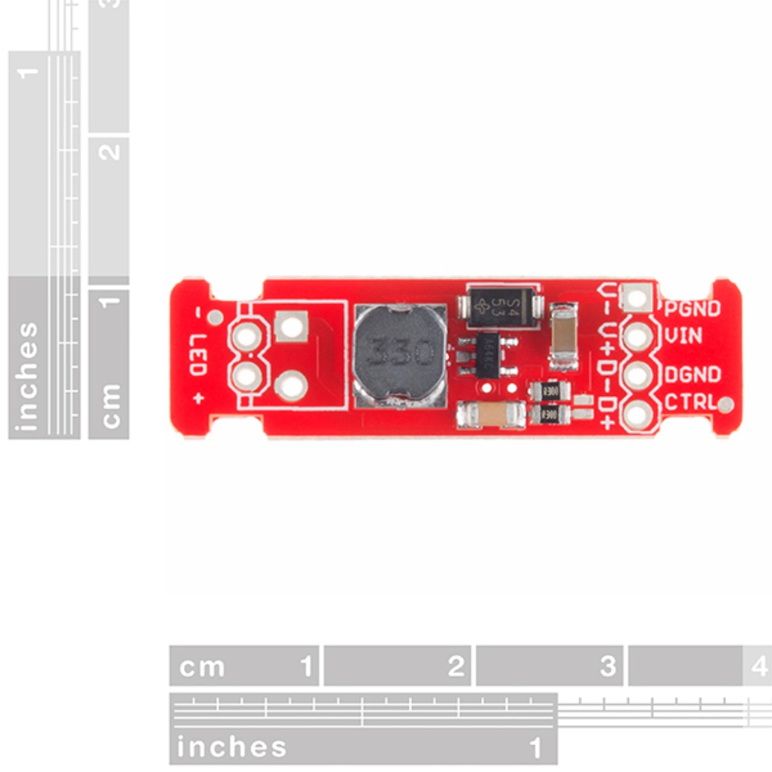
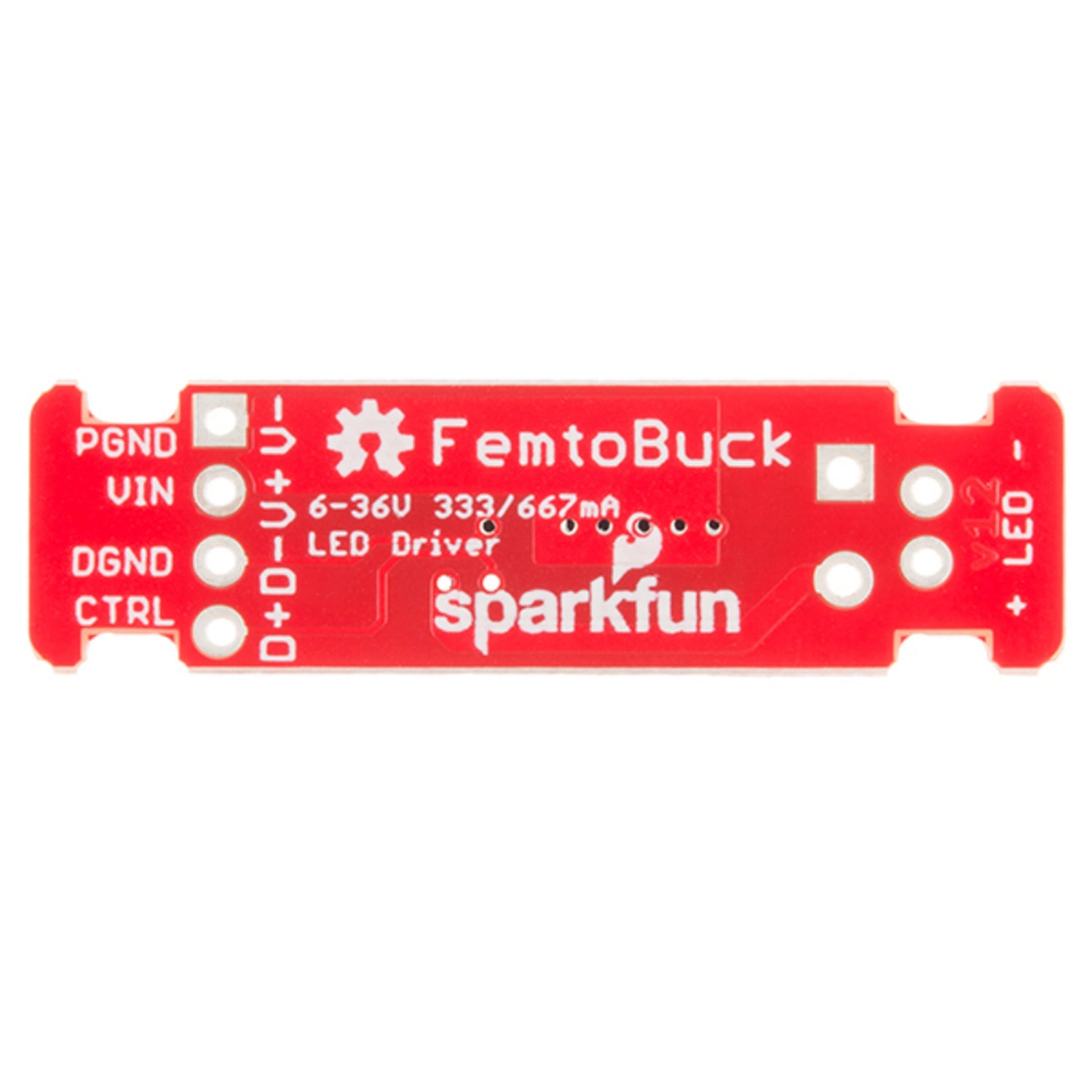
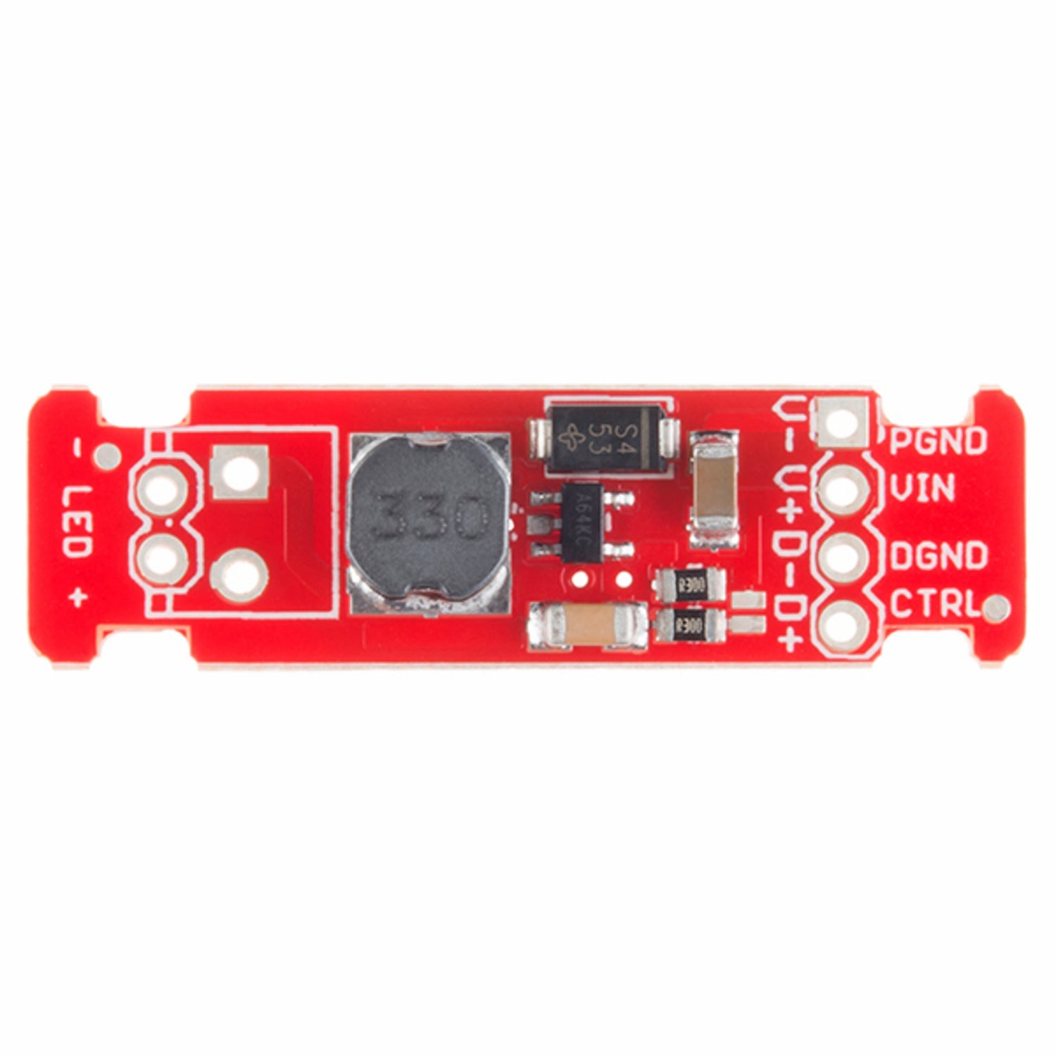
Meet the FemtoBuck, a compact single - output constant current LED driver. It can dim a single high - power LED channel from 0 - 350mA at up to 36V. You can control the dimming either through PWM or an analog signal ranging from 0 - 2.5V. This driver is based on the PicoBuck LED Driver co - developed with Ethan Zonca, but unlike the PicoBuck which blends three LEDs on different channels, the FemtoBuck controls just one. We've upped the voltage ratings of its parts, enabling the input voltage to cover the full 36V range of the AL8805 driver. As a constant current driver, the current drawn from the supply decreases as the supply voltage increases. Generally, it offers around 95% efficiency, depending on the input voltage. Each FemtoBuck has two inputs for power and dimming control, and a spot to install a 3.5mm screw terminal. There are small indents or 'ears' on both sides of the board, letting you use a zip tie to secure wires after soldering. This version comes with a small solder jumper that, when closed with solder, doubles the output current from 330mA to 660mA. Included documents are Schematic, Eagle Files, Hookup Guide, Datasheet (AL8805W5), and GitHub (Design Files).


Using the FemtoBuck LED driver is quite straightforward. First, connect the power input and dimming control pins to the appropriate sources. You can use either PWM or an analog signal for dimming, so choose the method that suits your setup. The 3.5mm screw terminal area on the board is where you can install the necessary connections. After soldering the wires, use the small indents or 'ears' on the sides of the board to secure the wires with a zip tie. When it comes to power, remember that as the supply voltage goes up, the current drawn from the supply will go down. Also, if you want to double the output current from 330mA to 660mA, you can close the small solder jumper with a bit of solder. For maintenance, keep the board clean and dry. Check the connections regularly to make sure they are secure. Refer to the included schematic, Eagle files, hookup guide, datasheet, and GitHub design files if you have any technical questions or need more detailed information.


